:max_bytes(150000):strip_icc()/examples-of-electrical-conductors-and-insulators-608315_v3-5b609152c9e77c004f6e8892.png)
10 Examples of Electrical Conductors and Insulators
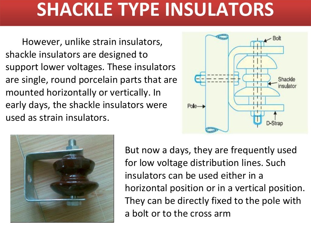
Suspension Insulator Strain Insulator Shackle Insulator Post-Insulator Stay Insulator Disc Insulator Pin Insulator This kind of insulator is used in distribution systems. The voltage capacity of this insulator is 11kV. It is designed with a high mechanical strength material. These are connected in vertical as well as horizontal positions.

Different Types of Insulators Used In Power Transmission Lines
Revise electrical charges, free electrons and the direction of conventional current, using circuit symbols, components and simple circuit diagrams.
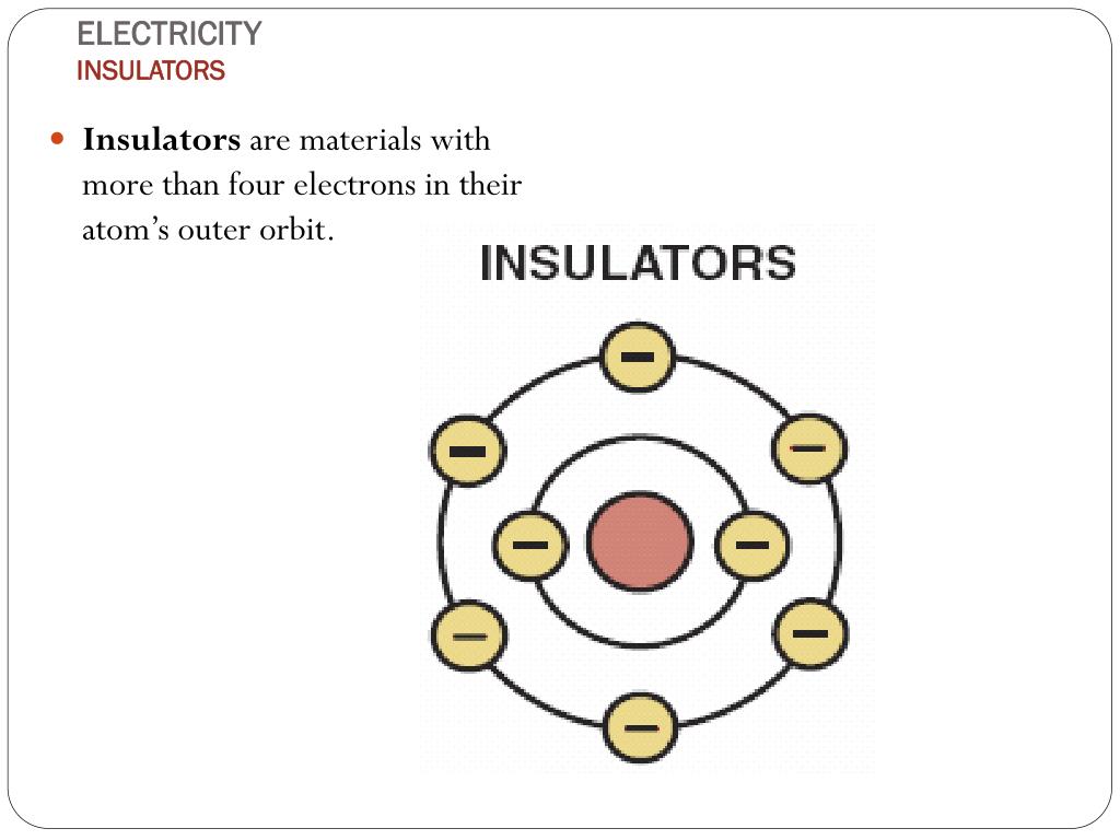
PPT Insulators and Conductors PowerPoint Presentation ID355613
The aim is to investigate the effectiveness of different materials as thermal insulators and the factors that may affect the thermal insulation properties of a material;. 6.2.4 Refraction Ray Diagrams; 6.2.5 Required Practical: Investigating Infrared Radiation; 6.2.6 EM Waves & Atoms; 6.2.7 Radio Waves; 6.2.8 Dangers of High-Energy EM Waves;

Insulator, Conductor, Semiconductor Explained Shubhanshu yadav. YouTube
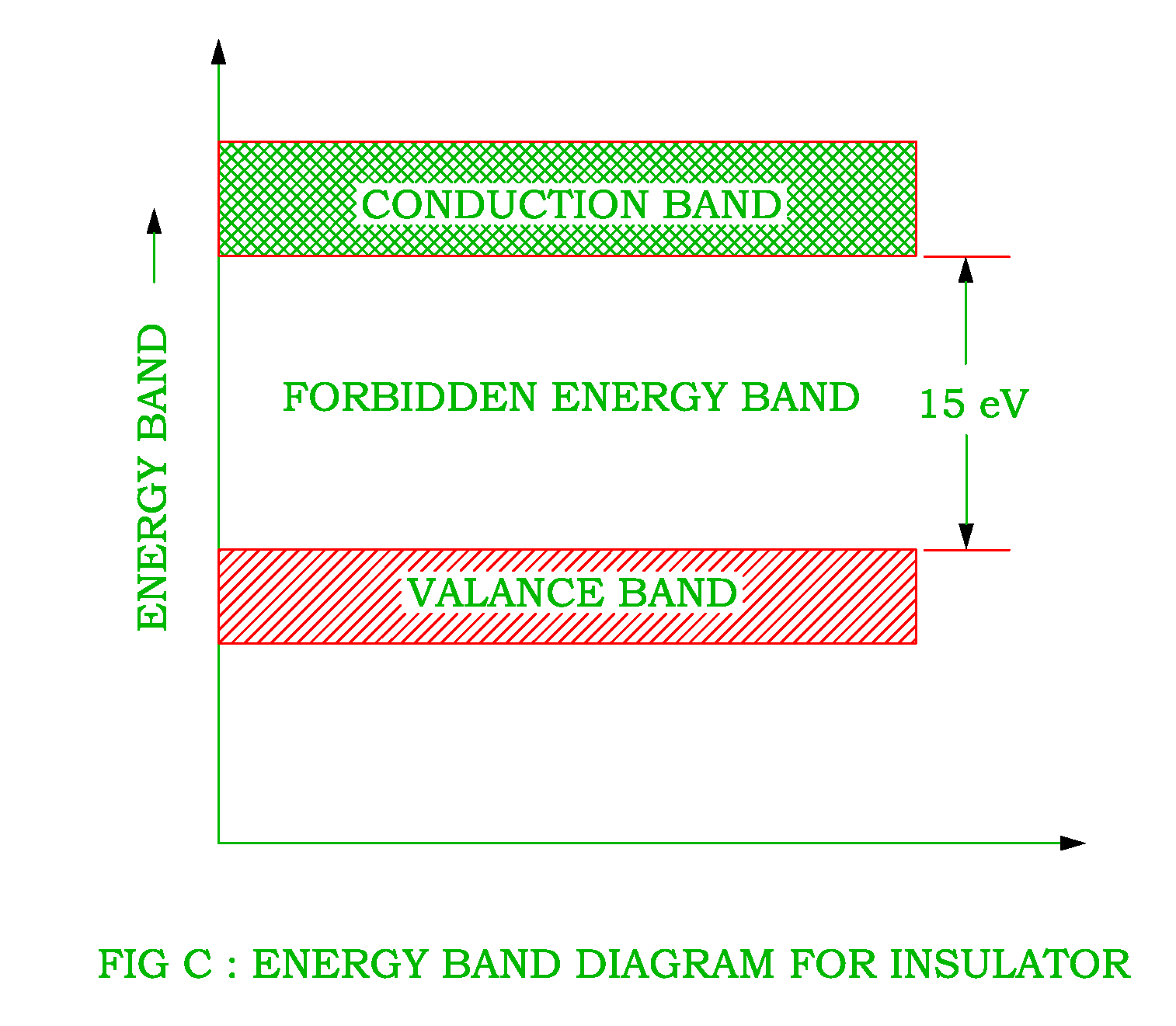
The Energy Band Diagram for Conductors Insulators and Semiconductors is shown in Fig. 1-13 show that insulators have a wide forbidden gap, semiconductors have a narrow forbidden gap, and conductors have no forbidden gap at all. In the case of insulators, there are practically no electrons in the conduction band, and the valence band is filled.
Cross section of suspension type porcelain insulator used for 154 kV... Download Scientific
Method 2 - Testing Different Thicknesses of Insulator: Wrap five beakers in varying thicknesses of one insulating material e.g. wrap each beaker in newspaper using one more sheet per beaker. Fill each beaker with warm water, record the initial temperature and cover each beaker with paper lids. Repeat the experiment as before, measuring the.

Conductor, Insulator and Semiconductor Play with electrons
Insulators, Conductors and Semiconductors (with Band Diagram) Categories Basic Electrical, Electronics Solid state materials can be classified into three groups: insulators, semiconductors conductors. Insulators have no free charge carriers available with them under normal conditions.

Electrical Systems High Voltage Insulator
The pin type insulator diagram is shown below. pin-insulator. These insulators are still used in 33 kV power distribution systems. These insulators are available in different parts like 1 part, 2 parts or 3 parts type based on the voltage of application. One part type is used in an 11 kV power distribution system where the entire insulator is a.
Conductors and Insulators Definition and Examples Electrical Academia
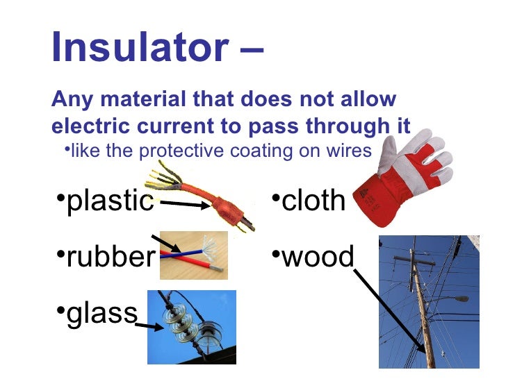
A conductor is a material that allows electrons to flow freely through it, making it useful for carrying electric current. An insulatoris a material that resists the flow of electrons, so it does not allow electric current to pass through it. Learn about how conductors and insulators work and how they are effected by changes in electrical current.
INSULATORS AND ITS TYPES
Question 1 of 4 Which object is an electrical insulator? copper wire metal paperclip plastic bottle • • • • Question 2 of 4 Which kind of material lets electricity flow through it? conductor.
Difference between Conductor Semiconductor and Insulator Electrical A2Z
3.5. Mott-Hubbard insulator. To carry the discussion we will start with an arrangement of monovalent atoms like hydrogen (H) in a cubic lattice with a lattice constant a as we have done earlier in section 3.2. The hydrogen atom at each lattice point carries one valence electron ( s electron) with it.
Structural diagrams of the four types of insulators. Download Scientific Diagram
A typical phase diagram for a metal-insulator transition is shown at the right for V 2 O 3. The octahedrally coordinated V 3+ ion has a d 2 electron count, so there are two unpaired spins per atom, and at low temperature the spins in the lattice order antiferromagnetically. As we learned in Chapter 8, above the Néel temperature an.
Conductors and insulators
Fig. 6 Band structure of insulators and semiconductors (molecular crystals); the conditions depicted reflect a molar crystal of carbon (diamond). Both insulators and semiconductors have the same basic band structure − the primary difference is the width of the forbidden energy gap (Eg) between the valence and the conduction band.
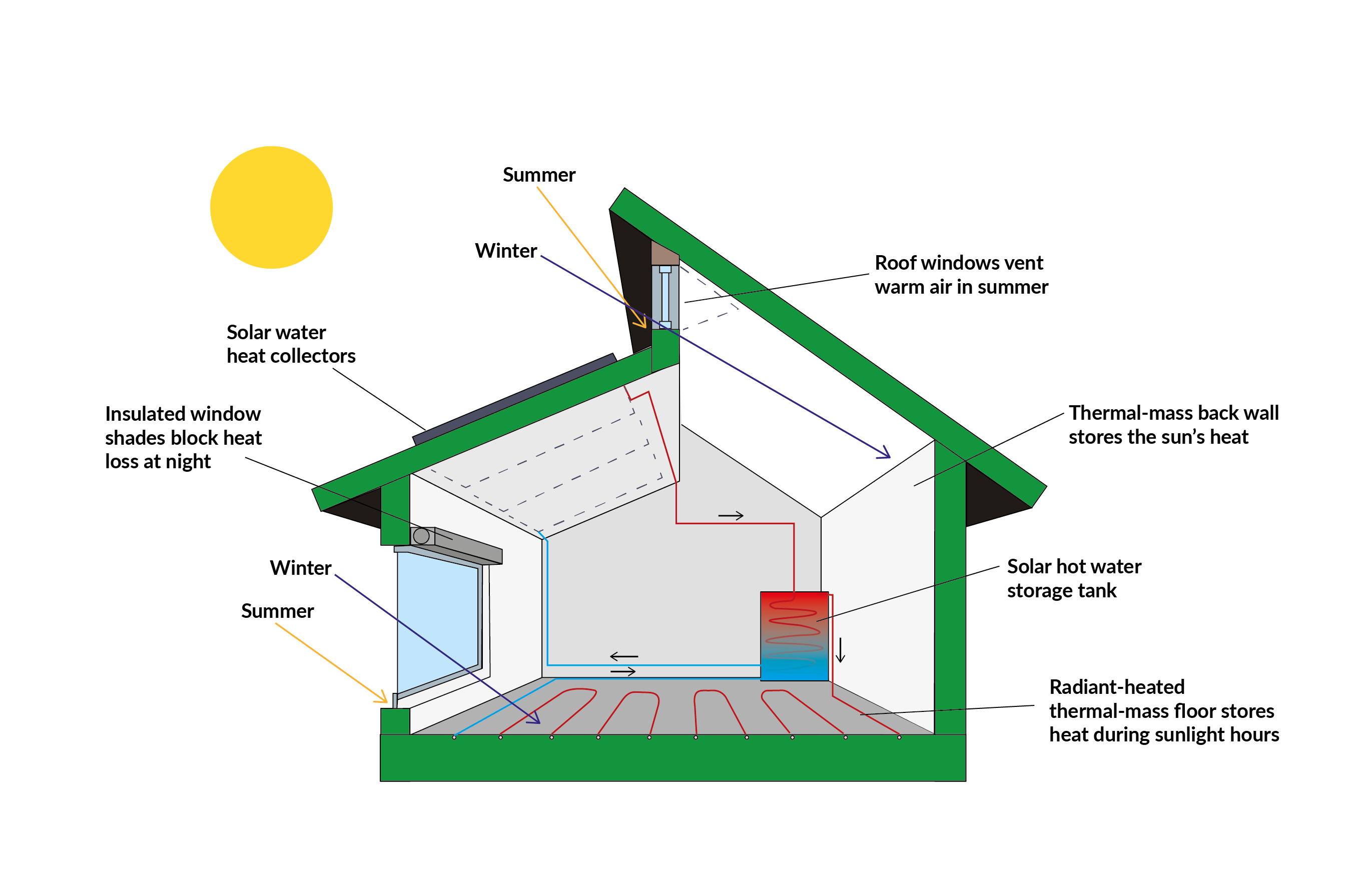
What is Passive House? A beginner's guide Insulation Superstore Help & Advice
April 25, 2021 by Electrical4U Contents Type of Insulators Used in Transmission lines There are 5 types of insulators used in transmission lines as overhead insulation: Pin Insulator Suspension Insulator Strain Insulator Stay Insulator Shackle Insulator Pin, Suspension, and Strain insulators are used in medium to high voltage systems.
PPT Chapter 3 PowerPoint Presentation, free download ID3887454
The probability of finding an electron in the conduction band is shown by the equation: P = 1 eΔE/RT + 1 (6.8B.1) (6.8B.1) P = 1 e Δ E / R T + 1. The ∆E in the equation stands for the change in energy or energy gap. t stands for the temperature, and R is a bonding constant. That equation and this table below show how the bigger difference.
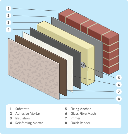
External Wall Insulation Everything You Need To Know Go Greena Blog
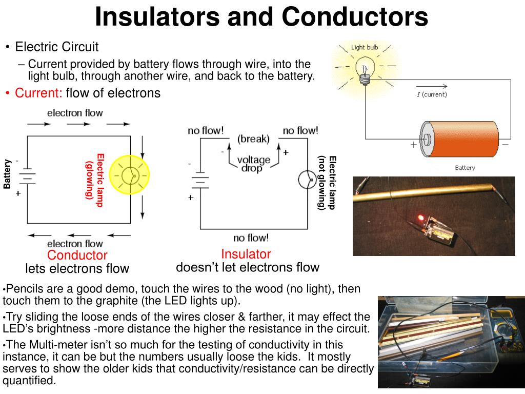
. The process of electrical current flowing through a wire is called conduction , and materials which conduct are called conductors. Most metals are good electrical conductors.
Electrical Revolution
In a conductor there are no band gaps between the valence and conduction bands. In some metals the conduction and valence bands partially overlap. This means that electrons can move freely between.
