XLR Pinout, Wiring Diagram Male and Female Connector ETechnoG
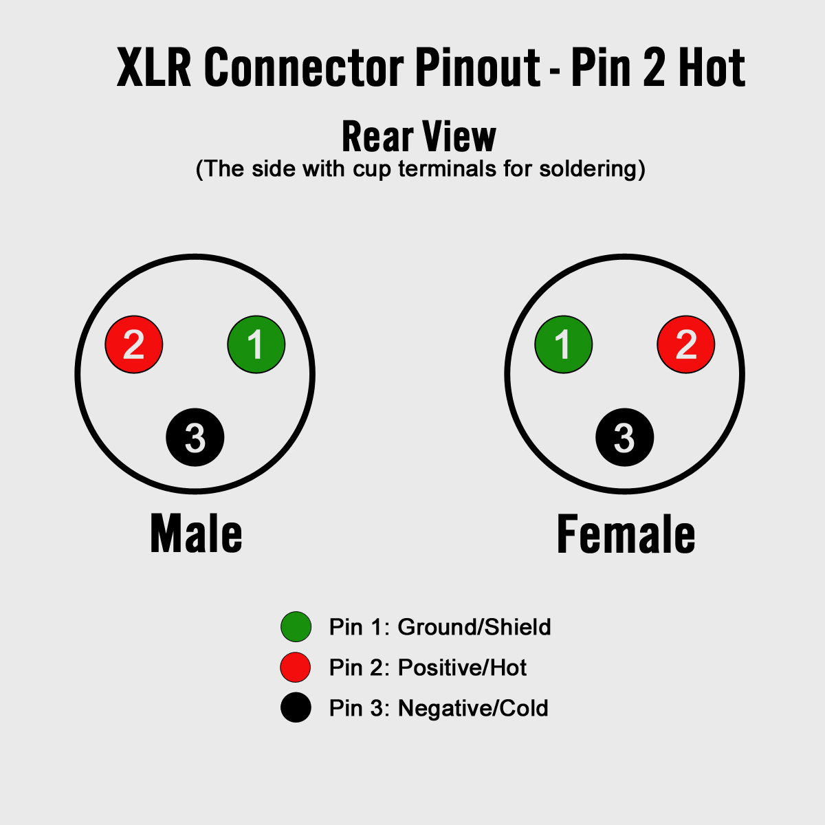
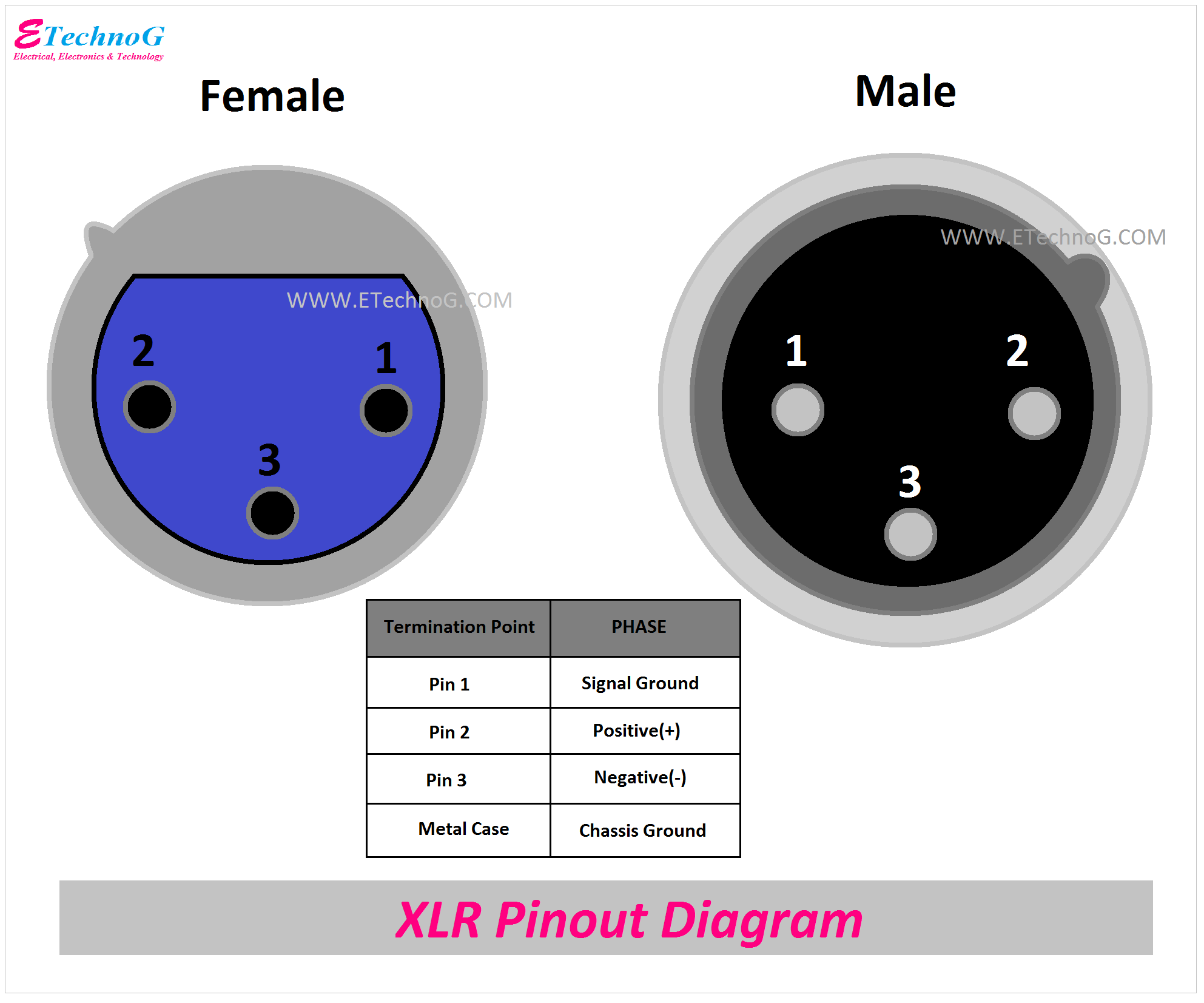
3 Pin XLR connectors are standard amongst line level and mic level audio applications. The above diagram shows you the pin numbering for both Male and Female XLR connectors, from the front and the rear view. (the rear view is the end you solder from) Here are the connections on each pin: Pin 1: Shield / Ground Pin 2: Positive Pin 3: Negative
shure sm57 wiring diagram
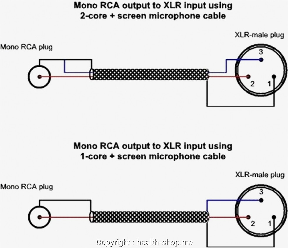
Shop Cable 3-Pin XLR Audio Pinout Three-pin XLR connectors are by far the most common style, and are an industry standard for balanced audio signals. The pinout listed below is the Audio Engineering Society (AES) industry standard for balanced audio XLR wiring. Sony 4-Pin XLR D.C. Power Supply Pinout 5-Pin XLR DMX Cable
How To Build Your Own Xlr Cables A Stepstep Guide Studio Diy Xlr Wiring Diagram Cadician
Hot Plugging XLR 3-Pin Wiring - Male/Female Type How do XLR connections work? What is the XLR pinout on A series models? What do the pins mean in XLR? What is the use of 5-pin XLR? What is the pin 1 on the XLR? What is the voltage of the XLR pinout? Is XLR DC or AC? How many ohms is XLR cable?
How to Build Your Own XLR Cables A Step by Step Guide Studio DIY — The Home Studio Archive
Anatomy of an XLR Connector. XLR connectors have different pin designs. The 3-pin version is commonly used for audio. Audio professionals use these cables for live shows and studio sessions because they are strong and can send signals over long distances. AV systems, lighting commands, and aviation headsets often use XLR-4 or 5-pin connectors.
XLR Pinout, Wiring Diagram Male and Female Connector ETechnoG
It has three pins: one for the ground, one for the positive signal, and one for the negative signal. 4-Pin XLR Connector: This type of XLR connector is used for DC power connections, and is commonly found on professional video cameras and other equipment. 5-Pin XLR Connector: This type of XLR connector is used for DMX lighting control, and is.
GMC Forum > Software Audio Production Blog
The XLR connector is renowned for its three-pin design, which ensures secure and balanced connections, effectively minimizing interference and noise. This makes it the preferred choice in live sound reinforcement, studio recording, and various audio applications where clarity and fidelity are paramount.

Dmx Cat5 Wiring
The XLR connectors are used mostly in professional audio and video electronics cabling applications. There is no common pinout - it's depends on application Reverse numbering?
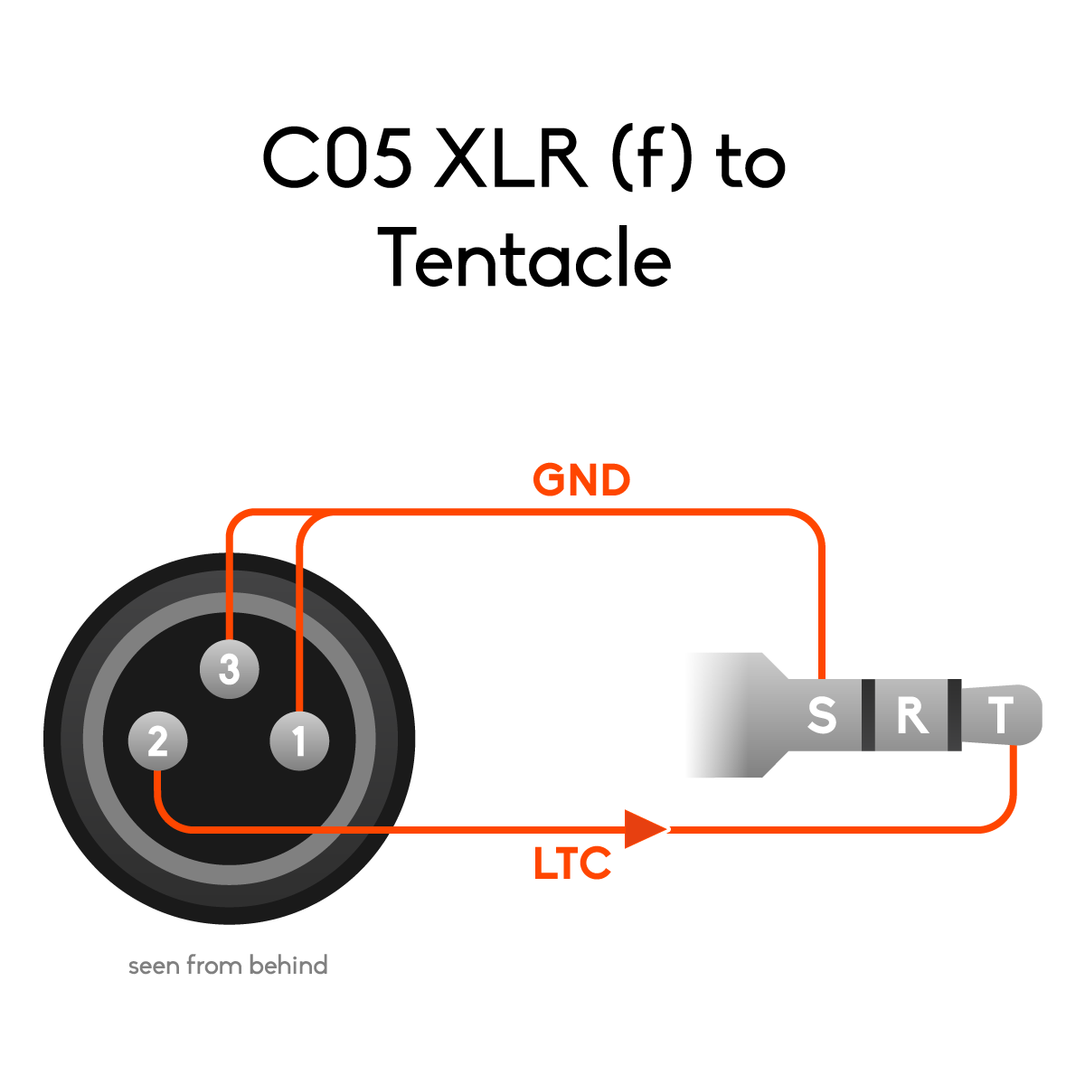
Pinouts and wiring diagrams for Tentacle cables Tentacle Sync
An XLR connector is a type of electrical connector that is mainly found on different types of audio, video, as well as stage lighting equipment at present. Being circular in design, these connectors consist of anything between 3 to 7 pins. In most cases, these audio connector types are related to balanced audio interconnection which includes.

Amphenol AX3F Female XLR Connector Nickel
According to 6 reports in our database (6 positive and 0 negative) the 4 pin XLR connector pinout should be correct. Is this pinout. correct. incorrect. 1 Related pinout(s) 5 pin XLR connector pinout; NO DIY devices. 2 Information source(s) DC connector; page 13; 4 pin XLR connector visual pinout: click to enlarge.

Mini Xlr Diagram T3af To T4af Xlr Pinouts Electronics Forum Circuits Projects And
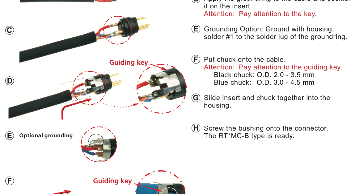
XLR Cable Connectors XLR Cable Connectors • Special version of the XX Series XLR cable connector for large cable diameters • Incorporates all the features of the XX product series • Rear boot features large opening for use with cable O.D. 8.0 - 10.0 mm • Bulk packed; must be ordered in multiples of 100 Large cable outlet Ergonomic latch
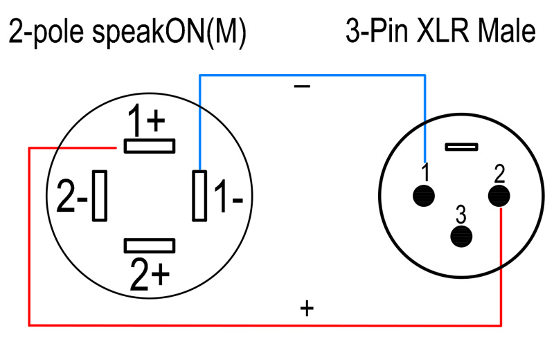
CPP11 2core 15AWG Speaker Link Cable Speakon XLR PropAudio
One way to get the best of all worlds, if you have the patience and dexterity, is to link pin‑1 to the XLR shell via a small capacitor (100pf polystyrene or similar, the value is not critical). This capacitor maintains the shell's grounding at RF frequencies, while presenting a high‑impedance path for circulating mains‑frequency ground currents.
Audio Technica Wiring Diagrams
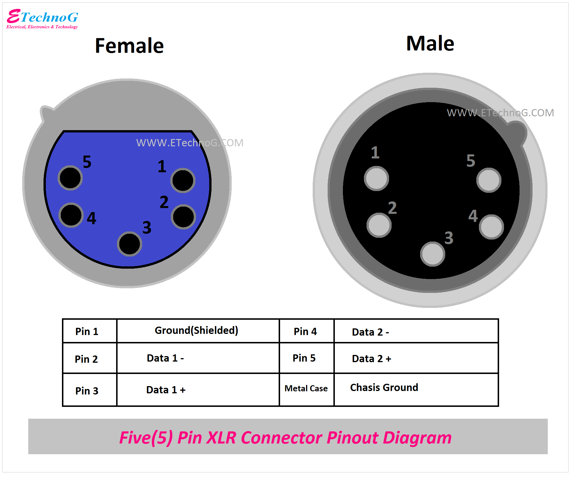
The three pin and five pin XLR pinout is a very standard connection used for audio (mic level & line level - 3 pin) and lighting control (DMX - 5-pin) applications. This article shows the XLR Pinout diagrams for both 3-pin and 5-pin connectors. You'll also discover each XLR pin's polarity. 3 Pin XLR Pinout
trs stereo headphone jack wiring
This method cancels out any electrical interference carried in the line. XLR4 Pinout XLR4 connector pinout The XLR connector with 4 pins is mostly used in intercom headsets. Among the four pins, two pins carry the headphone signals and the other two pins carry the microphone signals.
Xlr Cable Wiring
Step 1: Strip the ends of a cable using the wire cutters. Take off half an inch or 2cm of rubber insulation from the outside. Step 2: You'll see the thin wires. They form the internal insulation. Grab them all and twist them aside. So you get enough room to take the cloth insulation. Step 3: Strip the black and white wire.
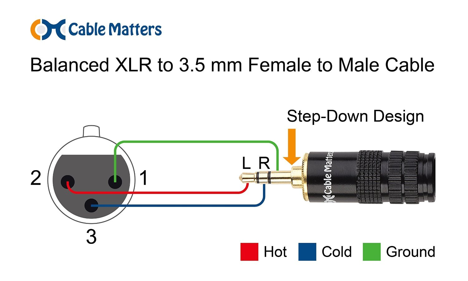
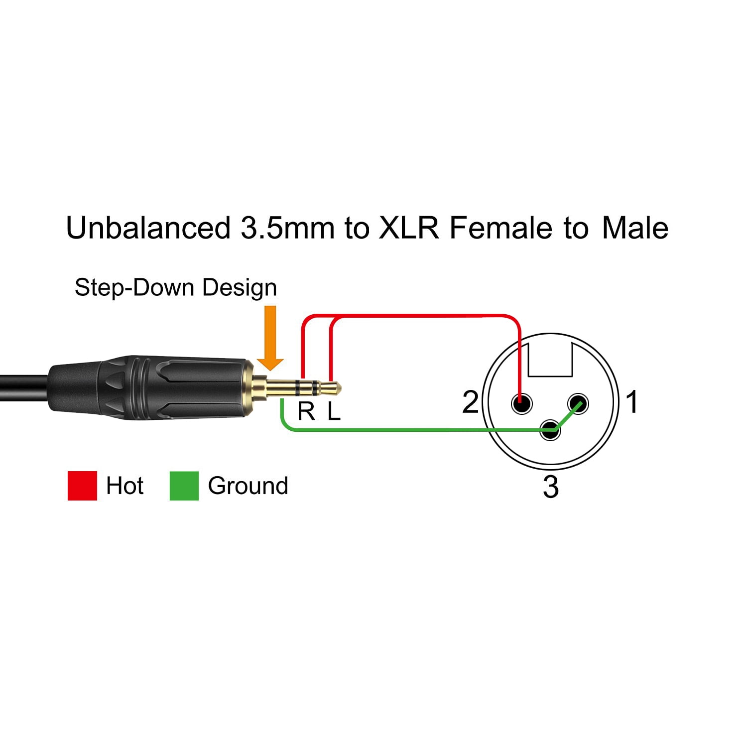
3.5 Mm Jack to Xlr Wiring Diagram autocardesign
What is the XLR Pinout? So, you want to unravel the mysteries of XLR pinout? Well, my friend, you're in for a treat! Let's take a closer look at the top secret inner workings of this audio connector. The Fantastic Trio: Pins 1, 2, and 3. Ah, the XLR connector! It's like a superhero team, with each pin having its own superpowers.

Notes and Volts What the Heck Is an XLR connector?
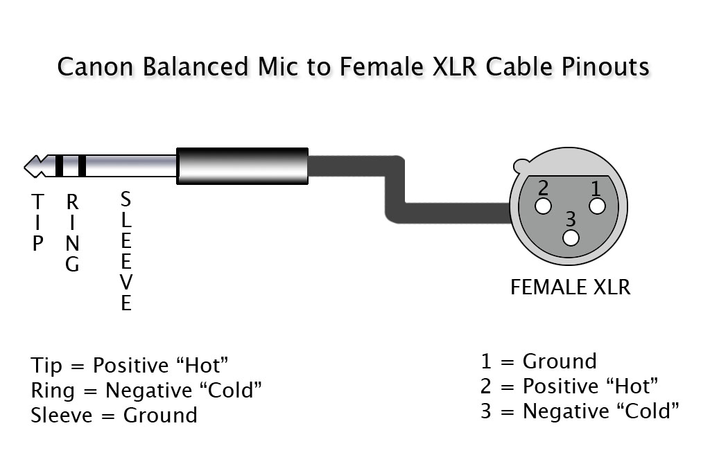
How to wire an XLR Connector (balanced) A balanced system is used in pro audio with an overall screen covering a twisted pair. Pin 2 on the XLR is 'hot' and carries the positive going signal, whilst pin 3 is 'cold' and provides the return.
