How to Create House Electrical Plan Easily
If you choose to sketch the electrical plans with paper and a pencil, it's recommended to study widely accepted electrical symbols to identify where wires, switches, relays, circuits, receptacles, and other individual electrical components are located in the home. This list of electrical drawing symbols is a great place to start. What You'll Need
Electrical drawing symbols in autocad jesdesk
An electrical plan (sometimes called an electrical drawing or wiring diagram) is a detailed and scaled diagram that illustrates the layout and placement of electrical components, fixtures, outlets, switches, and wiring within a building or space.

Electrical Symbols Free CAD Blocks And CAD Drawing
Understand the symbols: Familiarize yourself with the symbols used in electrical plans. Common symbols include a circle for a light fixture, a square for an outlet, a triangle for a switch, lines representing wires, and more. Refer to a key or legend provided on the plan to interpret the symbols accurately.
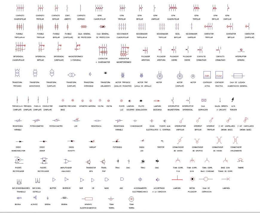
Free autocad electrical symbols sitfer
Electrical systems such as lights, switches, circuit breakers, distribution panels, and fixtures are denoted using various symbols described in legends. An electric planer is an instrument that helps to shave and shape wood. Legends contain abbreviations with symbols used for appliances, switches, panels, and other fixtures shown in a plan view.
How to Create House Electrical Plan Easily
All electrical symbols are only visible on 2D Floor Plans. They are part of our full product library, available for Pro and Team customers. This article explains how you can create your electrical floor plan with RoomSketcher. Just follow these four simple steps: Step 1: Draw your floor plan; Step 2: Add electrical symbols; Step 3: Add annotations
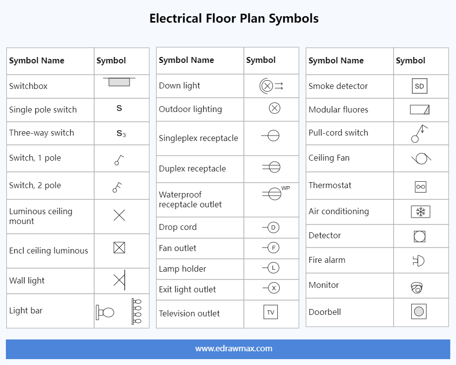
Electrical Floor Plan Symbols EdrawMax Templates
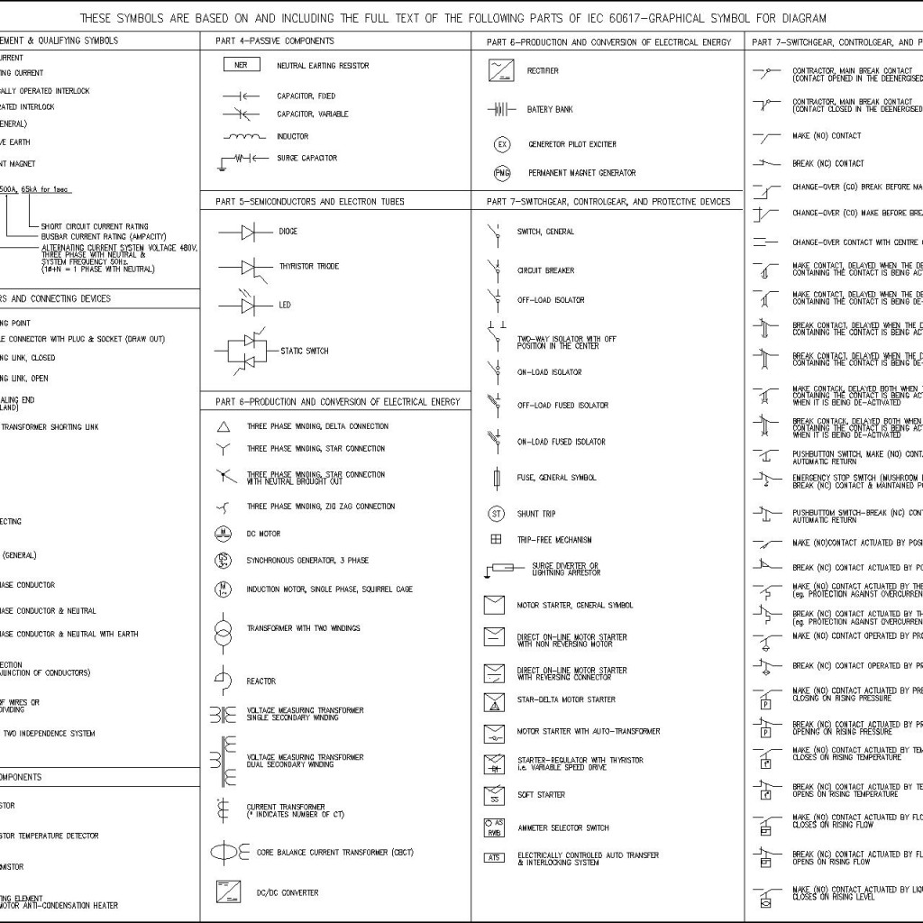
Basic electrical symbols contain earth electrode, cell, battery, resistor, etc. Whether you are a novice or a professional engineer, these basic symbols can help create accurate electrical and circuit diagrams in minutes. You can depict a complex electrical circuit with the standard and simplified electrical symbols.

Comment comprendre les symboles des plans d'étage Studio Galerie
Electrical plan symbols are universally recognized icons or drawings used to depict the various components of an electrical system. These symbols are commonly used in architectural plans such as reflective ceiling plans to denote specific electrical devices, circuits, and connections. What is standard electrical symbols?

Electrical Symbology Blueprint symbols, Electrical plan symbols
It is a type of technical drawing that delivers visual representation and describes circuits and electrical systems. It consists of electrical symbols and lines that showcase the engineer's electrical design to its clients. In short, an electrical plan describes the position of all the electrical apparatus.

electrical outlet symbol Floor plan symbols, Electrical symbols
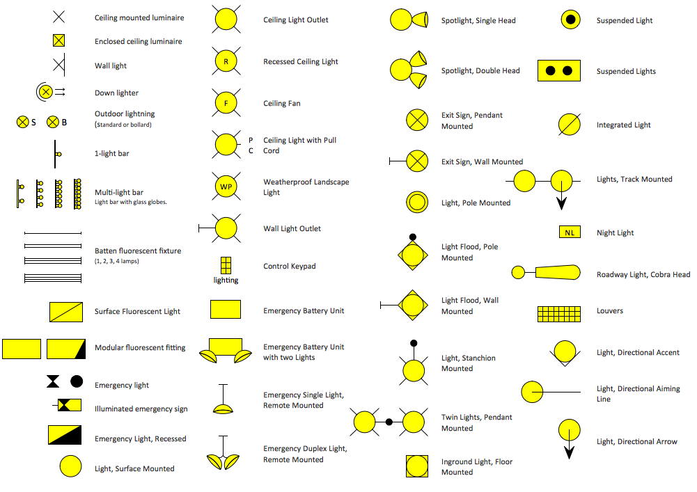
The basic symbol for most lights is a circle and, as with duplexes, variations on how it is drawn and abbreviations next to it convey additional and essential information. The key on the floor plans will explain the particular symbols used on any project.
Control Diagram Symbols Circuit Diagram Symbols Lucidchart These
Electrical Plan Symbols Design & Documentation > Construction Documentation Every engineering office uses their own set of electrical symbols; however, the symbols below are fairly common across many offices. Refer to the legend sheet in your set of plans for special symbols used in a particular set. Article Contents Power Symbols Lighting Symbols

Home Electrical Wiring Symbols
Electrical symbols are used for universal recognition of the building plan by different persons who will be working on the construction. Not all possible electric symbols used on a certain plan, so the symbols used in the current home plan are included to a legend.
Home Electrical Plan, Electrical Symbols
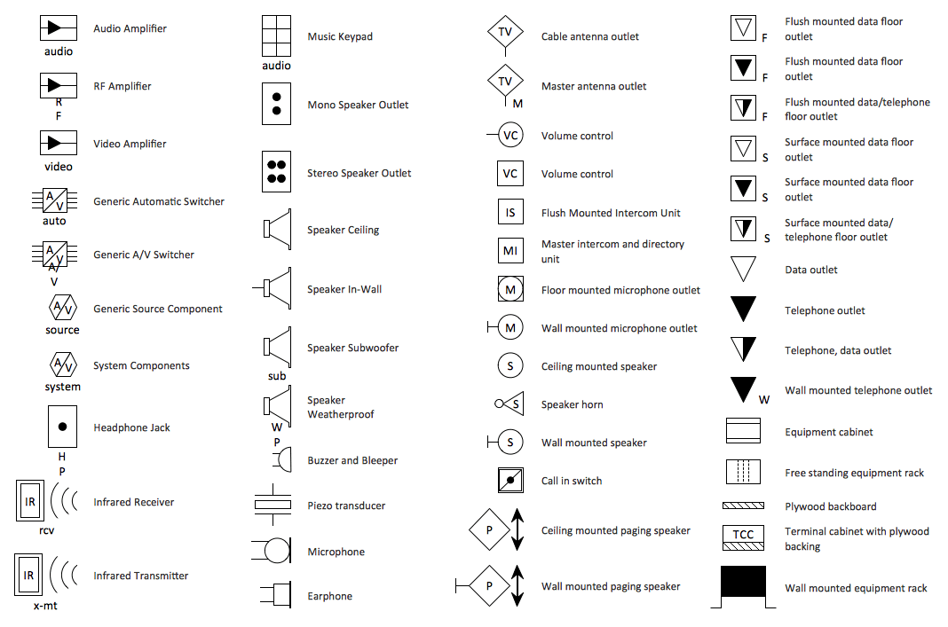
2. Outlets and Switches. Outlets and switches are the most common elements in an electrical plan. Electrical outlets, or sockets and other outlets are where you plug in appliances and electronic devices. Switches, conversely, control the flow of electricity to light fixtures. The electrical symbols used for these elements are standardized.

Important Ideas Building Plan Electrical Symbols, Amazing!
An electrical plan is a detailed drawing or diagram that shows the locations of all the circuits, lights, receptacles and other electrical components in a building. Professional electricians rely on electrical plans when installing or renovating electrical systems.
Electric Wiring Symbols
An electrical plan is a visual electrical blueprint where all the electrical points of a building will be located. It describes the connection between the circuits, the number of switches and the location of their outlets, the position of lighting fixtures and any other electrical appliances.

Electrical Symbols Construction Drawings
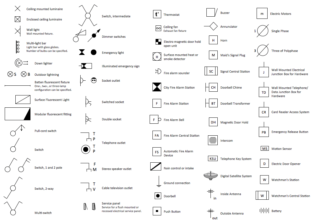
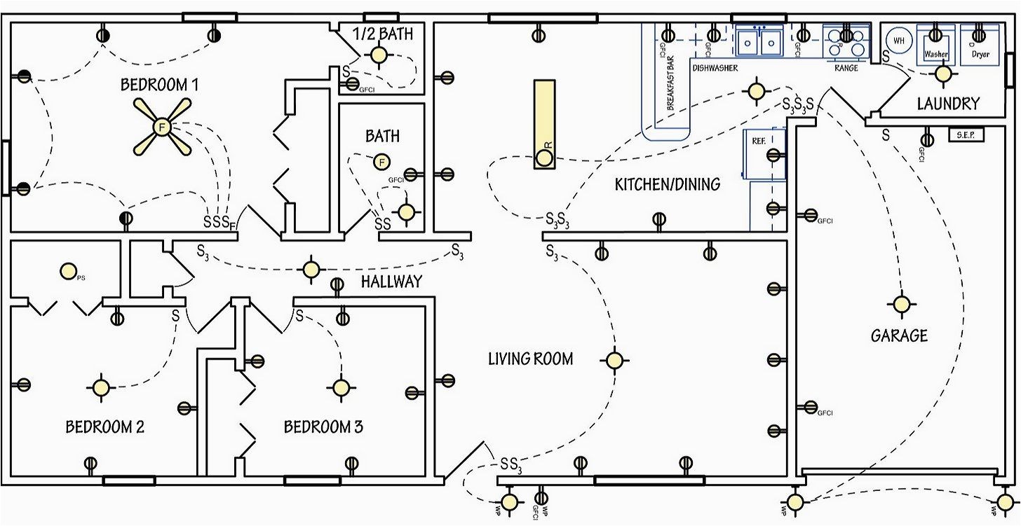
Electrical symbols are used on home electrical wiring plans in order to show the location, control point (s), and type of electrical devices required at those locations. These symbols, which are drawn on top of the floor plan, show lighting outlets, receptacle outlets, special purpose outlets, fan outlets and switches.

Free CAD Blocks Electrical Symbols
The most commonly used electrical blueprint symbols including plug outlets, switches, lights and other special symbols such as door bells and smoke detectors are shown in the figure below. Note: Explanations for common household electrical items such as three-way switches and switched duplex plug outlets are below the figure. Notes:
